
Energy Saving with Tube Inserts for Heat Exchangers
Refiners are continuously challenged to improve energy efficiency and reducing CO2 emissions. PETROVAL solves this challenge by offering tailor-made solutions to its customers through Tube Inserts Technology.
Founded in 1990, PETROVAL developed and became the world leader in terms of dense loading technologies by launching the first generation of DENSICAT, the leading dense loading catalyst machine. Due to DENSICAT’s great success, PETROVAL was able to rapidly grow into new refining service and technology lines, including making its mark in tube insert technologies in 1993. Tube inserts are designed and manufactured specifically to a refinery’s system to maximize heat transfer, to reduce heat exchanger fouling, CO2 emissions and to offer an average six-month payback PETROVAL tube inserts are now installed in more than 150 refineries worldwide.
The energy efficiency of (petro)chemical and refining industrial plants is highly dependent on heat exchanger efficiencies. A plant’s heat recovery, estimated during the design process, represents significant operational margins. However, the estimated heat recovery can differ greatly from design once fouling occurs in heat exchanger networks. Fouling leads to loss of heat recovery, pressure drop increases and throughput reductions, ultimately resulting in mandatory maintenance shutdowns.
Tube insert technologies are proven solutions that can benefit a heat exchanger network in terms of increased heat transfer coefficient, a reduced fouling rate and stability of pressure drop.
This study considers fouling in crude oil preheat trains caused via asphaltene deposition and/or coke formation on hot surfaces.
In these tests, heat exchangers forming part of preheat trains in two different refineries are equipped with Turbotal® inserts for study A and Spirelf® inserts for Study B. Their performances are monitored over different periods (between two and four years) and compared to the previous run durations under similar process conditions.
Study A – Heat Transfer Enhancement and Fouling Mitigation with TURBOTAL®
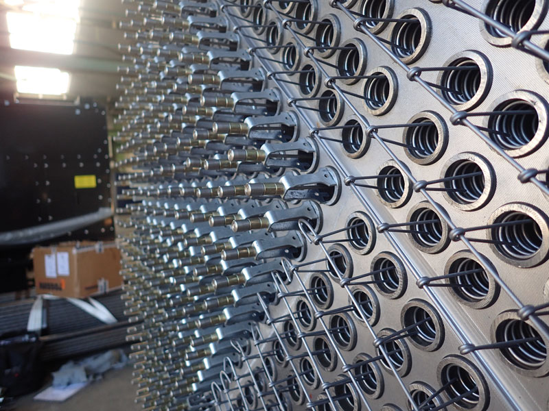
Turbotal® is a rotating device hooked on a fixed head and attached on the tube end on the inlet side (see Fig. 1). This system is a continuous online cleaning device whose purpose is to reduce the fouling layer at the tube walls by mean of mechanical effects. Turbotal® uses the energy of the flow running through the tubes to rotate the device in the range of 1000 rpm with limited impact on pressure drop.

The last pairs of heat exchangers just before the furnace were suffering severe fouling over a period of less than one year. The four heat exchangers were equipped with Turbotal® and operated in the same range of process conditions as before (see Table 1). The performance monitored was compared with the previous data. The comparative trend of the outlet temperature is presented in Fig. 4.
| Position in the train | Just before the furnace |
| Bundle number | 2 branches of 2 bundles |
| Tube number / bundle: | 1 164 |
| Tube length: | 6,100 mm |
| OD / BWG: | 1” / 12 |
| Product tube / shell side: | Crude / Atmospheric residue |
| Flow rate (tube side): | 580 / 830 / 920 t/h |
| Flow velocity (tube side): | 1.2 to 2.2 m/s |
| Tube insert: | Turbotal® |
| Replacement frequency: | Every 2 years |
| Table 1. – Heat exchangers design and operating conditions. | |

The trend presented in Fig. 3 shows an increased outlet temperature at start of run (SOR) of 3°C under clean conditions. This gain is related to the additional turbulence generated by the rotation of the Turbotal® resulting in an increased heat transfer coefficient on the tube side by 80% compared to bare tube.
The rate of decrease of the feed outlet temperature is almost three times slower with Turbotal® compared to bare tubes; this phenomenon is due to fouling mitigation throughout the run. The Turbotal® significantly reduces the fouling rate but cannot prevent all fouling deposition to occur. Previous studies identify fouling resistance with Turbotal® results with an asymptotic profile corresponding to the distance between the tube wall and the Turbotal® device.
A payback analysis was performed on this application evaluating energy gains compared to the cost of the Turbotal® device and installation. An average gain of more than 10°C was achieved during the first year leading to energy gain valuing 1.4 Million € to compare with an estimated investment of 100,000 €. The payback calculated considering only energy gain costs is in the range of 1 month. However, additional operating expenses would have to be considered such as reduction of maintenance cost (mechanical cleaning avoided), production losses (reduction of throughput during partial shutdown for cleaning) and cost of CO2 emissions at the furnaces (around 45 €/t today, the cost of CO2 emissions should increase up to 100 €/t in the coming decade).
Study B – Extensive Run Duration with SPIRELF®
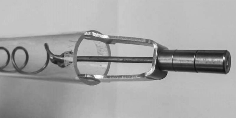
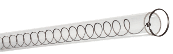
Spirelf® is a vibrating device fixed on both tube ends by a fixing wire (see Fig. 2). This system is also a continuous online cleaning device whose purpose is to reduce the fouling layer on the tube walls by means of mechanical effects. Spirelf® uses the energy of the flow running through the tubes and converts it into vibrations of the device both radially and longitudinally. Additional pressure drop generated by the device is limited and can increase potential run duration up to six years.
The last pair of heat exchangers just before the furnace was suffering severe fouling over a period of less than one year. The two heat exchangers were equipped with Spirelf® and operated in the same range of process conditions as before (see Table 2). The performance monitored was compared with the previous data. The comparative trends of the heat transfer coefficients of each tube bundle and the crude flowrate will be presented in the results section.
| Position in the train | Just before the furnace |
| Bundle number | 1 branch of 2 bundles |
| Tube number / bundle: | 710 |
| Tube length: | 9,144 mm |
| OD / BWG: | 3/4” / 14 |
| Product tube / shell side: | Crude / Atmospheric residue |
| Flow rate (tube side): | 309 t/h |
| Flow velocity (tube side): | 1.7 m/s |
| Tube insert: | Spirelf® |
| Replacement frequency: | Every 3 years |
| Table 2. – Heat exchangers design and operating conditions. | |
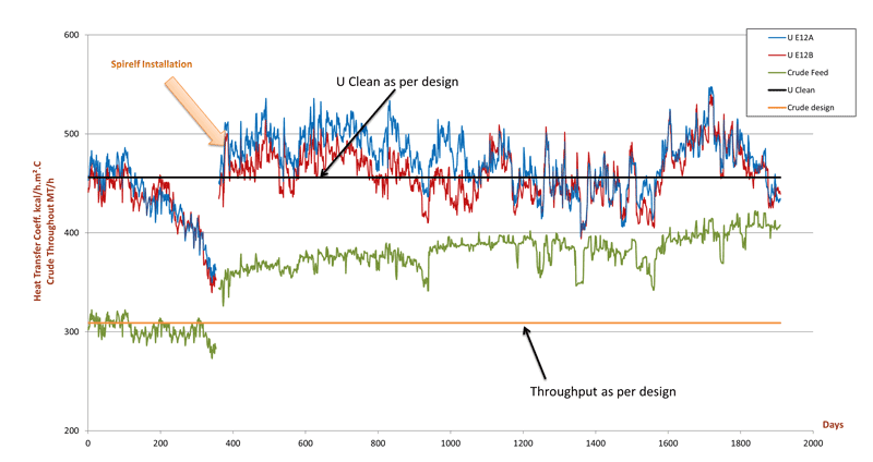
Fig. 4 – Trend of crude feed and OHTC for both tube bundles compared to previous run with bare tubes.
The trend presented in Fig. 4 shows a first run period, for which the OHTC (blue and red trends) decrease sharply from clean design level to only 70% within one year. After Spirelf® installation, the flow rate across the heat exchangers remains close to design value, resulting in a lower coil inlet temperature (CIT) at the furnace.
Spirelf® devices were implemented during a turnaround. The performance of each tube bundle is represented on the same trend. The OHTC with Spirelf® is operating at design value and up to 22% above design for 500 days.
Over this period, the crude flow rate was pushed above design value, gradually increasing from +10% to +25% for 900 days. As the performance of other exchangers declined, feed rate was slightly reduced for a planned cleaning period without ceasing operations of the bundles equipped with Spirelf®.
Once the complete train was back in service at 940 days, the feed rate was pushed back to +25% of design for 400 days with OHTC of both heat exchangers still performing at or above design. A second maintenance period was completed on other heat exchangers without ceasing operations of heat exchangers equipped with Spirelf®.
After restarting at full capacity at 1400 days, performance of the heat exchangers equipped with Spirelf® began declining leading to reduction in crude flow rate.
The exchangers equipped with Spirelf® were by-passed at 1600 days for a flush (in this case, recirculation of hot gasoil). This flushing operation was carried out without opening the heat exchangers with the objective being to loosen and remove deposits.
Instantly after this flushing operation, the heat exchangers were reintroduced in the process and unit throughput increased up to +35% of design with OHTC for each heat exchanger operating above design by +22%. The heat exchangers were still in service at the time this paper was authored.
Implementation of Spirelf® in this system considerably increased run duration from one year to more than four years. Three maintenance periods were avoided during this extended run.
The performance of the heat exchangers considerably improved compared to before the installation of Spirelf®, resulting in significant energy savings.
Unit flow rate was debottlenecked +35% of design value with acceptable feed preheat temperatures.
Conclusions
Significant improvements related to the use of tube inserts are highlighted in these studies. These conclusions can be drawn from field data analysis.
For both applications, run duration with the tube inserts is at least doubled compared to the same run with bare tubes under similar operating conditions.
For each case, heat exchanger performance was increased in terms of heat transfer.
Exchanger performance improvement was measured via outlet temperature (Study A) where the gain on clean conditions was 3°C and averaged a gain of more than 10°C over the run duration.
For Study B the gain on OHTC was measured, reaching +22% compared with -30% for bare tubes in less than a year.
Tube inserts technologies can be used to debottleneck feed limitations in a unit’s preheat train (like in Study B). Note: as identified in Study B, the capability to debottleneck is also dependent on cleanliness and availability of the entire preheat train, not only the exchangers equipped with inserts technologies.
The benefits from these technologies are evident in extending run duration between cleaning shutdowns, increasing heat transfer coefficient, reducing fouling factor and stability of pressure drop. From an economic viewpoint, payback is generated by four improvements: the energy saved in the preheat train (via increase in heat transfer), the reduction in maintenance cost (reduced cleaning frequency), the increased throughput and the reduced CO2 emissions (considering the cost of CO2 emissions will drastically increase from 45 €/t up to 100 €/t in the coming decade).
The use of these technologies in existing heat exchangers networks can allow Refiners and Petrochemical Complexes to improve their energy efficiency and reduce their carbon footprint for a sustainable future.